Hardware / Build 01
Raspberry Pi 5.
Four drives.
One compact NAS.
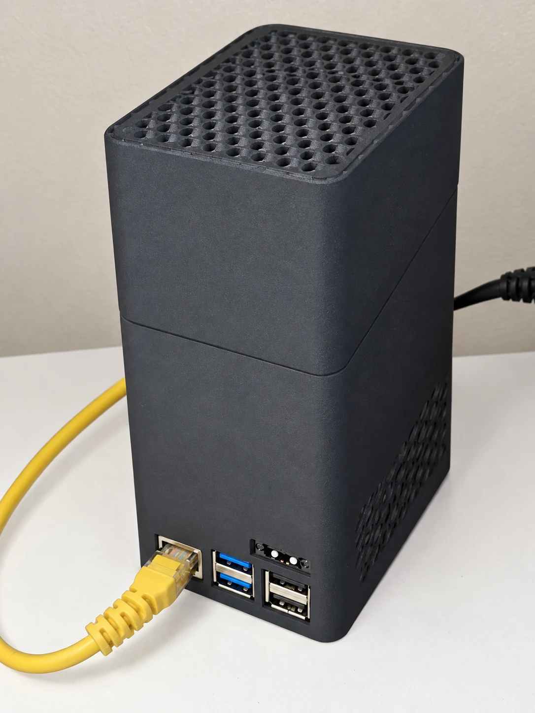
The first real-world PaNasMs build: a Raspberry Pi 5, a Radxa Penta SATA HAT and four 2.5-inch hard drives in a 3D-printed enclosure.
This is the owner's working NAS and our development system. The assembly photos show how it came together; the cooling section explains both two-wire and four-wire fan connections.
- Board
- Pi 5 · 8 GB
- Storage
- 4 × 1 TB HDD
- Array
- Linux RAID 5
The parts
What is inside
| Part | This build |
|---|---|
| Computer | Raspberry Pi 5 with 8 GB RAM. |
| Storage board | Radxa Penta SATA HAT, linked to the Pi's PCIe connector by an FPC cable. |
| Data drives | Four Western Digital WD10JFCX 1 TB, 2.5-inch SATA HDDs. |
| System drive | microSD, separate from the data array. Card model and capacity are not specified in this build record. |
| CPU cooling | Raspberry Pi 5 Active Cooler, separate from the disk-bay fan. |
| Power | 12 V supply to the HAT, which also powers the Pi. The purchase record lists Mean Well GST90A12-P1M (12 V, 6.67 A); the installed label still needs confirmation. |
| Enclosure | Printed tower with lower I/O openings, a vertical drive bay and a ventilated top cover. |
| Operating system | Raspberry Pi OS with PaNasMs installed on top. Linux mdadm manages the RAID 5 array. |
Four 1 TB drives in RAID 5 provide roughly 3 TB (about 2.7 TiB) before filesystem overhead. This is capacity arithmetic, not a performance benchmark. RAID is not a backup.
The HAT offers four internal SATA connections and an additional eSATA connection. This enclosure uses the four internal positions. See Radxa's hardware documentation for the board and its revision-specific pin allocation.
From boards to enclosure
The assembly
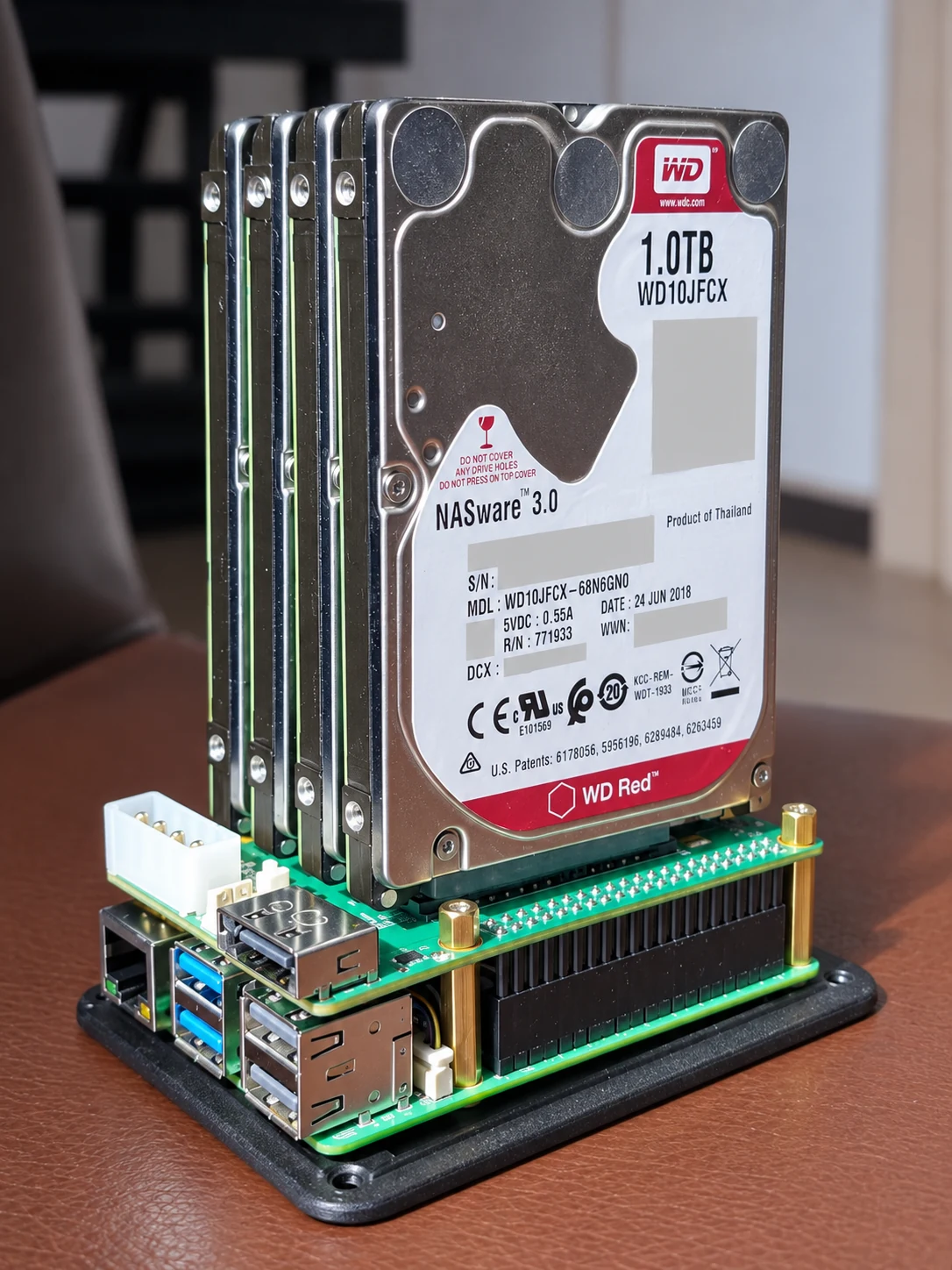
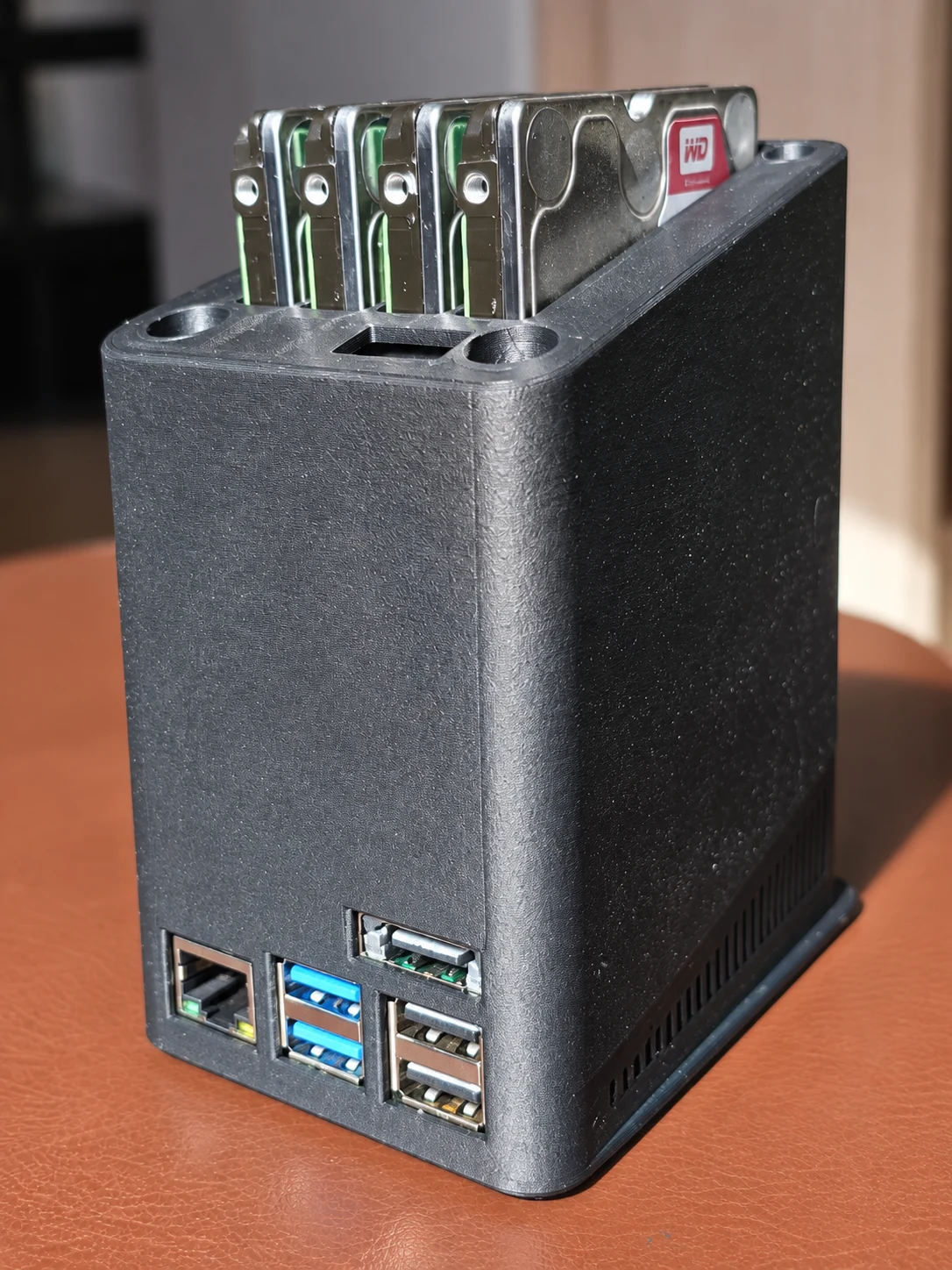
The Pi sits below the HAT, with the drives standing above it. Keep the PCIe ribbon clear of sharp bends, provide mechanical support for the drives and leave the case vents unobstructed. Check standoff height, connector clearance and wiring before closing the cover.
These images were cropped and retouched from the owner's September 2026 photos using AI-assisted image editing. They illustrate assembly stages, not exact electrical connections. Use the numbered wiring tables below for those.
CAD and printable parts are being organised separately. A final reproducible print set, fastener list and third-party model licences are still being checked; this page does not provide a validated case download or claim that a 60 mm replacement fan fits the current cover.
Disk-bay cooling
Two ways to control the fan
The CPU cooler and the disk-bay fan are independent. PaNasMs already controls the disk-bay fan from disk temperatures. The two arrangements below use different electrical signals and cannot share the same controller configuration.
Two-wire fan + MOSFET
A 5010 or 5015 fan powered at 5 V or 12 V. GPIO27 controls an external switch in the fan's ground lead.
Wiring and limitations ↓ Separate PWM inputFour-wire PWM fan
Noctua NF-A6x15 PWM, 12 V. Continuous power, a separate 25 kHz speed-control wire and RPM feedback.
Wire colours and pin map ↓Option 1 · Two-wire fan and external PWM switch
The existing arrangement uses the Arduino-compatible MOSFET module identified by the owner as “535”. A two-wire 5010 (50 × 50 × 10 mm) or 5015 (50 × 50 × 15 mm) is the intended form factor. Match its rated voltage to the supply and verify mounting clearance; the deeper 5015 has not been fit-tested.
The module switches the negative lead. GPIO27 is a 3.3 V control signal only; it never supplies the motor. “535” is not a complete electrical specification: check your module's terminal labels, ratings and 3.3 V input compatibility.
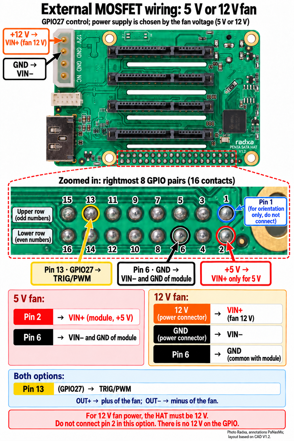
Connect directly to the GPIO solder joints
| Connection | 5 V fan | 12 V fan |
|---|---|---|
| Module VIN+ | Physical pin 2: +5 V | Confirmed +12 V on the large HAT power connector. Leave pin 2 disconnected. |
| Module VIN− | Physical pin 6: GND | GND on the HAT power connector |
| Module control GND | Physical pin 6; common with supply negative | |
| Module TRIG/PWM | Physical pin 13: GPIO27 | |
| Fan positive / negative | Module OUT+ / OUT− respectively | |
Alternative: use the small 2×5 connector
On this connector, pin 4 is +5 V, pin 9 is GND and pin 8 is the PWM route. These are its own connector numbers, not 40-pin GPIO numbers. For a 12 V fan, take power from the large power connector instead of pin 4.
The older Radxa schematic routes pin 8 through R563 to physical pin 13, with an alternative route via R573 to pin 33. Current generic documentation calls it PWM_33. Verify which route is populated on your revision; do not assume every HAT connects it to GPIO27. Radxa schematic.
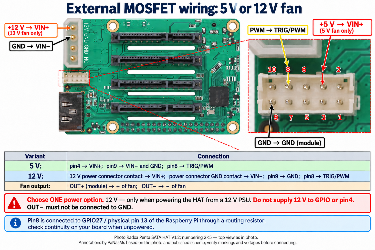
Never join OUT− directly to ground: that bypasses the switch. Never feed a 5 V fan with 12 V, even at a low duty cycle. The 40-pin header has no 12 V rail.
What works today, and what does not
The existing controller uses approximately 40 Hz software PWM on GPIO27 and the hottest active disk's temperature. The UI percentage is requested duty, not measured RPM: a two-wire fan has no tachometer feedback.
Low-duty tests of the previous fan produced crackling, and a higher-frequency test stopped it. This is a documented existing topology, not a recommendation that every two-wire fan will run quietly on power PWM. The fan must support supply switching and start reliably at the selected settings. The 12 V variant has not been validated with a replacement fan on this NAS.
Option 2 · Noctua with native four-wire PWM
The four-wire option uses the Noctua NF-A6x15 PWM, 12 V, 60 × 60 × 15 mm. It uses continuous power and a separate control input. The old MOSFET module is not used. Check mounting clearance for the 60 mm fan before fitting it to the cover.
| Fan wire | Function | Connect to |
|---|---|---|
| Black · contact 1 | Ground | HAT power connector GND; second contact from top in the illustration |
| Yellow · contact 2 | Continuous +12 V | Top contact of the illustrated HAT power connector, marked 12V |
| Green · contact 3 | Tachometer output | Physical pin 18 / GPIO24, input with internal pull-up to 3.3 V |
| Blue · contact 4 | PWM input | Physical pin 12 / GPIO18, hardware PWM at 25 kHz |
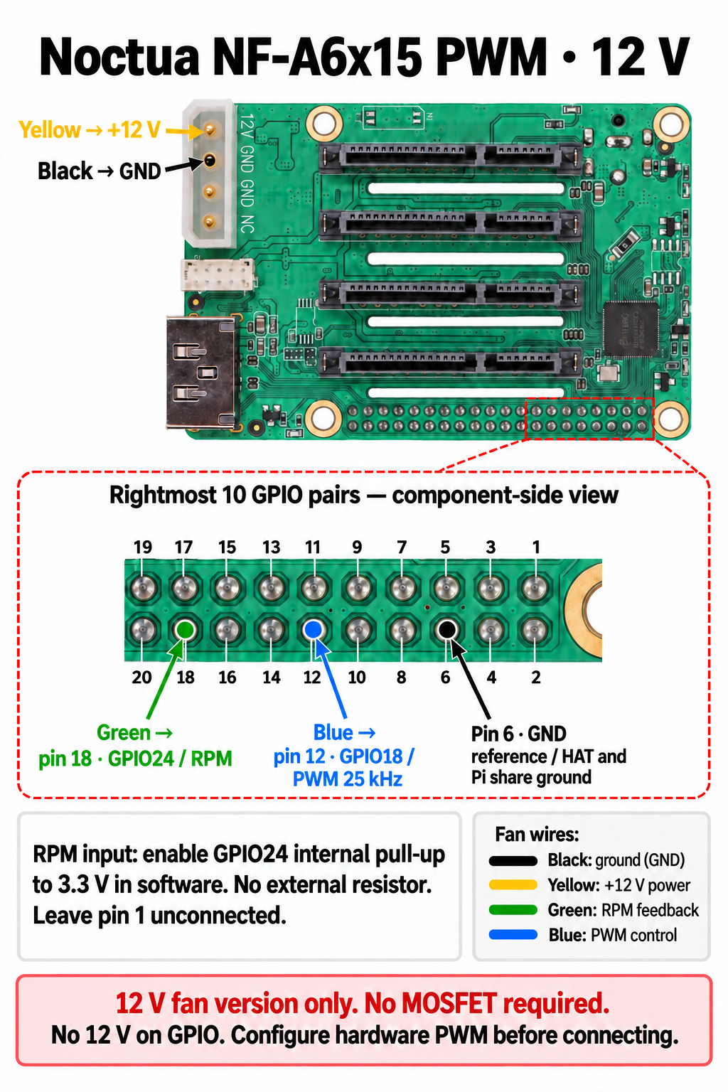
Noctua's PWM input accepts 3.3 V logic. The target is 25 kHz (40,000 ns period), with a specified 21–28 kHz range. Its tachometer is open-collector and produces two pulses per revolution. See Noctua's PWM specification and fan specifications.
Keep yellow and black continuously powered; do not reuse the old GPIO27 low-frequency supply switching. Physical pin 6 is a ground reference, and physical pin 1 stays unconnected. Never pull the tach signal up to 5 V or 12 V. Verify RPM reliability with the internal pull-up.
On Pi 5, select the RP1 hardware PWM function for GPIO18 and check pin ownership and overlays first. Do not copy a Pi 4 PWM channel number or assume a fixed pwmchip index. Removing the PWM signal normally gives full speed; a signal stuck low is a different failure and needs explicit handling. Power may remain on after OS shutdown.
Before powering on
- Disconnect all power, including possible USB back-power, before soldering or moving wires.
- Check the board revision and pin-1 orientation. In these component-side illustrations the rightmost inner joint is pin 1; the rightmost outer joint is pin 2.
- Verify contact continuity while unpowered and the supply voltage before connecting the fan. The illustrated large power connector reads 12 V, GND, GND, NC from top to bottom.
- Insulate the joints, add strain relief and inspect for solder bridges. Do not solder into mating socket contacts.
- Check fan voltage, mechanical clearance, starting current and airflow. A similarly named Noctua 5V PWM model must not receive 12 V.
- For the four-wire fan, configure and verify the 25 kHz PWM output before automatic use. Test startup, minimum duty, temperature response and failure handling with the case assembled.
Sources and image credits
Build inventory and operating status come from the owner's project records. Assembly photos: Pavlo, cropped and retouched with the built-in image editor; original photos remain private. Published photo derivatives are covered by this site's PolyForm Noncommercial licence.
Wiring illustrations: Radxa reference photograph with AI-assisted PaNasMs annotations and schematic pin enlargements. Source: Radxa Penta SATA HAT image, Radxa documentation, licensed CC BY 4.0. Adapted wiring images retain that attribution; they are not precision manufacturing drawings.
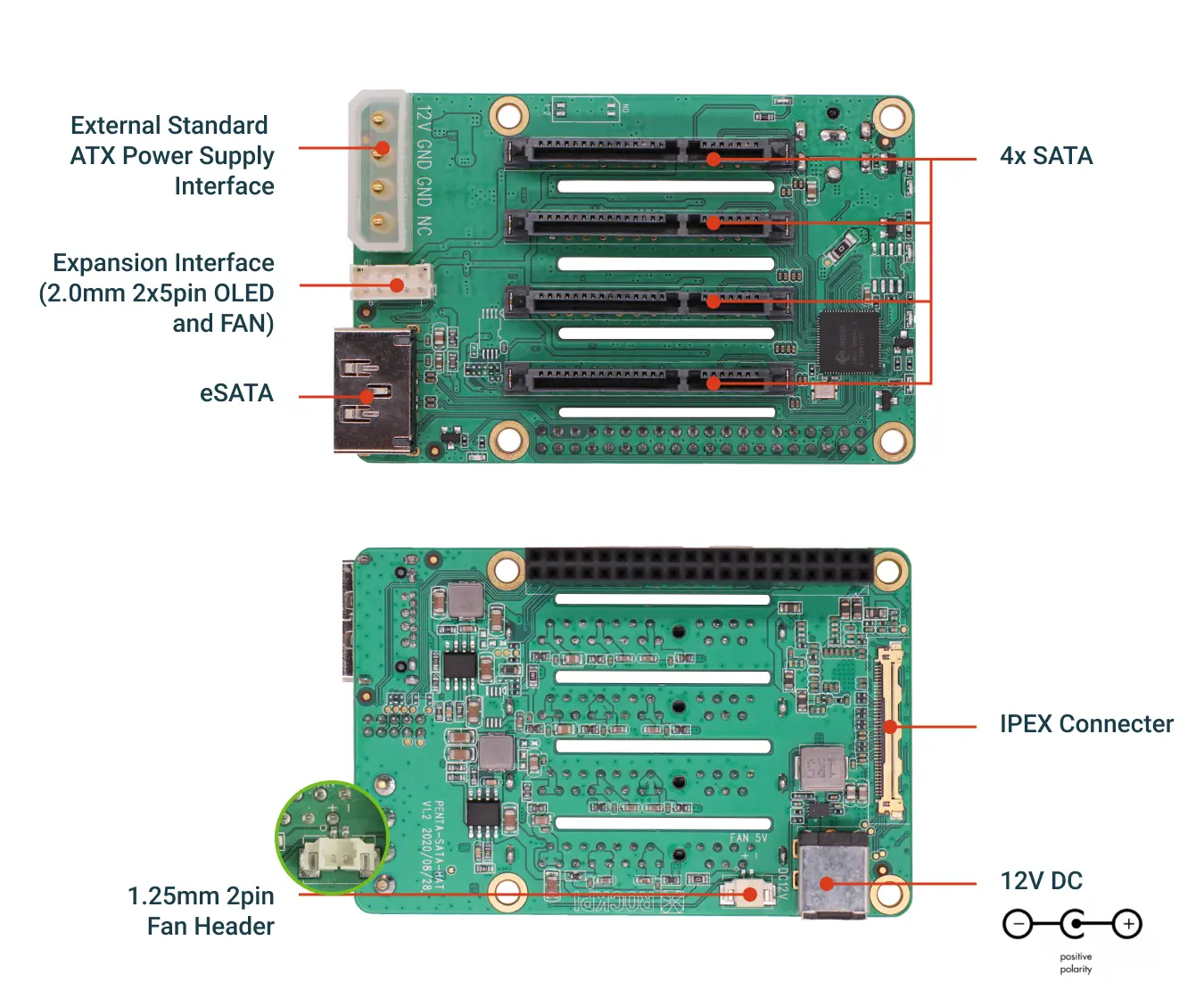
Additional references: Raspberry Pi GPIO documentation · RP1 peripherals · Radxa V1.2 mechanical reference.
Build record: September 2026. One working NAS, not a certification of every board revision, disk, fan or case combination.